The Application of Superheated Steam to Locomotives
The Application of Superheated Steam to Locomotives |
|||||
|
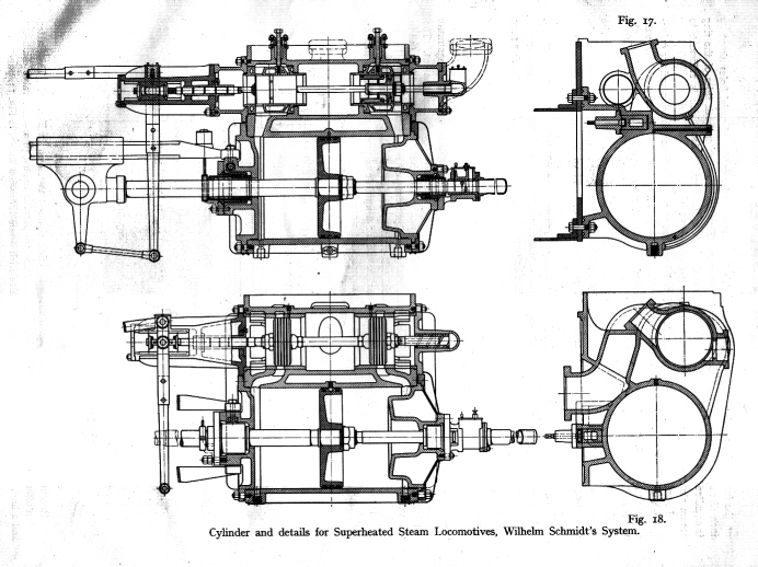
DETAILS OF CYLINDERS FOR HIGH TEMPERATURE APPLICATION The use of superheated steam required a design change of those parts which come in contact with
the steam, such as cylinders, valves, pistons, stuffing boxes etc. In order to operate reliably. Dr. Schmidt took on this
detailed re-design. His efforts have met with such success, that the wear and tear of the components operating with highly
superheated steam did not exceed wear and tear, one experienced with saturated steam. Even on trial runs, when the engines
worked with such high steam temperatures as 415 ° C (720 ° F) no troubles
whatsoever were experienced. The most suitable temperature was at about 345 ° (650 °
F). It was measured at the valve chest by means of a reliable pyrometer with the dial fixed in the cab of the engine. When
the regulator throttled the steam, the pyrometer indicated a fall in the temperature of the steam in the valve chest, but
not the temperature of the steam in the boiler. A description of these remodelled engine details are shown below:
|
||||||||||||||||||||||||||||||||||||||||||||||||||||||
|
Special care had to be taken to obviate unnecessary thickening of walls of cylinder
castings. The cylinder walls also had to be separated from the cylinder casting proper, in order that injurious strains due
to in-flowing superheated steam and the unnecessary transmission of heat and consequent heat losses may be prevented. That
would have been the case had the piston valve casing and the cylinder been made in one.
In order to avoid overheating of the stuffing boxes, special provision is made for cooling
them by air, refer to related figures Details of the the Schmidt Patent Piston Valves
Piston valves must be used in locomotives when highly superheated steam is employed.
Dr. Schmidt has introduced two distinct patterns specially designed by him with inside admission for use in superheater locomotives.
These types are:
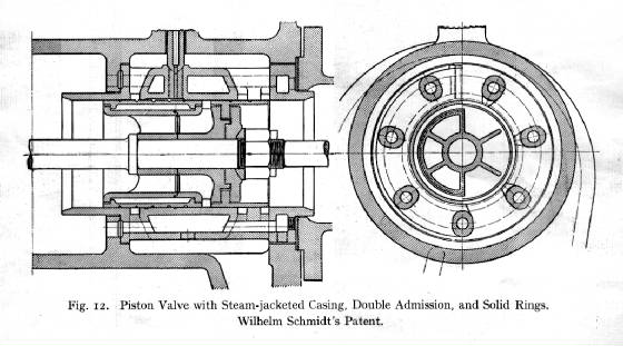
(a) Piston valve with steam jacketed casing, which had double admission and solid piston
rings. It required up-to-date machinery and particularly exact workmanship (b) Piston valve with balanced split rings and valve covers pressed on by steam.
A. Piston Valve with Steam-Jacketed Casing, Double Admission
and Solid Piston Rings When using superheated steam it is desirable that the steam-distributing valves should work with a
minimum of friction, so as to be subject to the least amount of wear and tear. It also should require the smallest amount
of lubricant. These conditions induced Dr. Schmidt to use solid rings. With such rings, the difference in the amount of expansion
between the piston and the casing was considerable, and it was found necessary to reduce the size of the valve to a minimum.
Therefore, double inside admission ports have been adopted, by means of which it has been possible to keep the diameter of
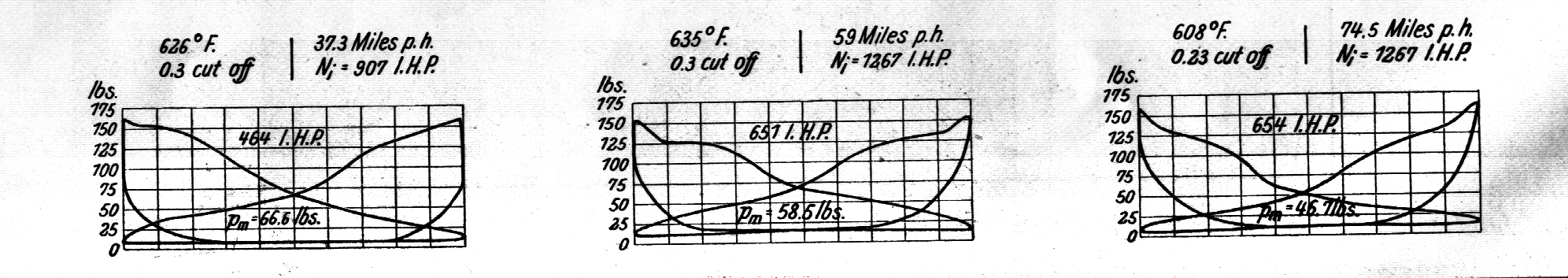
the valve almost as small as that of the exhaust pipe. The diameter of the piston valve was optimized to 150 mm (6 inches),
proved by tests and indicator cards as shown below.
The weight of the test train, excluding engine and tender was 361 tons. The gross weight, including engine
and tender was 467 tons. The power shown on the diagrams is for both cylinders. The well known disadvantage of ordinary valves, namely their tendency to seize if too tightly fitted, has been avoided
in the Schmidt valve by making the walls of the casing hollow, and by heating them with live steam. As this ensures uniform
expansion the valve can be fitted so accurately that any steam that does not leak past is reduced to a minimum, and this loss
is more than compensated for by the reduction of friction. Preliminary warming up the casing before starting the engine is
unnecessary. Owing to the absence of friction, the wear of this type of piston is very small: in fact after a year and a half
such valves have shown no trace of wear.
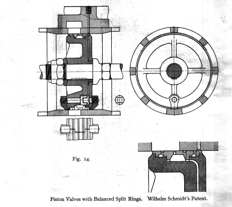
B. Piston Valve with Balanced Split Rings
Although excellent results have been obtained with the solid ring type piston valve, many railway
companies desired a valve with equal performance but which would not require such a high degree of accuracy in the manufacturing
process. Dr. Schmidt therefore developed a split ring valve, which operated satisfactorily for a number of years. The rings
used in this type of valve were wider, as shown in Fig.
Experience has proved that narrow rings are not to be recommended for use with highly superheated
steam. Wide rings overcome these difficulties but they had other disadvantages. By the steam leaking behind the rings, the
rings are forced with great pressure against the liner and excessive wear soon takes place. In the new Schmidt split ring
valve the advantages of the wide split ring valve were retained, avoiding the drawbacks of high wear and leakage. This result
was achieved by providing several steam-tight spaces on the inside of each ring, which are connected with the steam port by
means of small holes at the circumference of the ring. Thus, most of the time, the pressure on both sides of the rings is
equalized, so that the ring is only pressed against the liner by its own tension. This pressure is adequate to secure steam
tightness, with very small friction and the wear and tear is almost infinitesimal.
Steam tightness is given as long as the split is located opposite the broad bridge of the liner and
as long as the ring has some elasticity. The cut in the ring is protected on the outside with a cover, and the screws holding
the cover prevent the ring against turning. Most railways using superheated steam used the valves of this type. Prior to 1908 the piston described above has been made with a trick channel, as shown in Fig.16. This design offers
the advantage of double admission and therefore permits the use of a small valve diameter and higher piston speed when compared
with a valve shown in Fig.14.
|
||||||||||||||||||||||||||||||||||||||||||||||||||||||
|
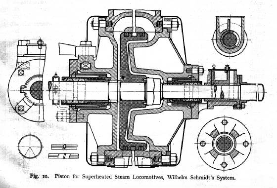
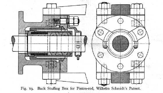
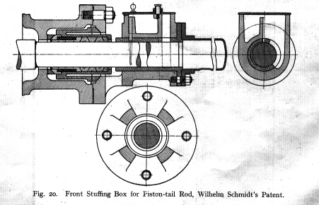
SELF-ADJUSTING AIR COOLED STUFFING BOX WITH SPHERICALLY SEATED PACKING RINGS Figures 19 and 20 below show a back stuffing box and a front stuffing box respectively. The type of stuffing
boxes previously used did not allow for lateral movement of the piston rod without considerable steam leakages.
Both Figures show the spherically seated packing ring and the sleeve containing the white metal packing rings.
The cast iron ground ring is cored out to obtain cooling by air over its entire length. Cooling of the stuffing box was forcibly
demonstrated during early trials of the superheated steam engine, in which the white metal rings melted as soon as a high
degree of superheat was reached. Figure 10 shows the complete arrangement of the stuffing box, including the cylinder. Special Arrangements for running Superheated Steam Locomotives with Regulator closed Piston valves have the distinct disadvantage of being unable to lift from the port face like ordinary valves, when the
engine is drifting, i.e. running with the regulator closed. Therefore, if there is excessive compression after the steam is
shut off, piston valves will offer no relief and pounding of the cylinders is the consequence. Both Figures show the spherically seated packing ring and the sleeve containing the white metal packing rings.
The cast iron ground ring is cored out to obtain cooling by air over its entire length. Cooling of the stuffing box was forcibly
demonstrated during early trials of the superheated steam engine, in which the white metal rings melted as soon as a high
degree of superheat was reached. Figure 10 (above) shows the complete arrangement of the stuffing boxes, including the cylinder.
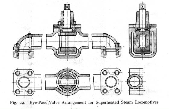
To prevent this, and at the same time to avoid the vacuum forming action of the piston, the bypass arrangement
shown in Fig. 22 has successfully been applied to the Schmidt superheater locomotives. It consists of a steam passage, which
connects both cylinder ends, and which is kept closed by a cylindrical cock so long as the engine is running under steam.
The cock is manually opened as soon as the regulator is shut. The bypass connects the front and the back of the piston, thus
preventing the formation of vacuum and excessive compression. The spindles of the bypass valves of both cylinders are coupled
together and are activated by an arrangement on the foot- plate. In addition of the bypass valves, suitably arranged snifting valves must be provided, in order to prevent overheating of
the cylinders during comparatively long period of drifting, and also to prevent back sucking from the smoke box, whereby furnace
gases and grit might be drawn into the cylinders and valves.
|
||||||||||||||||||||||||||||||||||||||||||||||||||||||